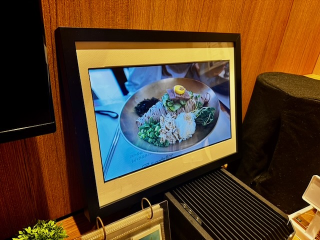
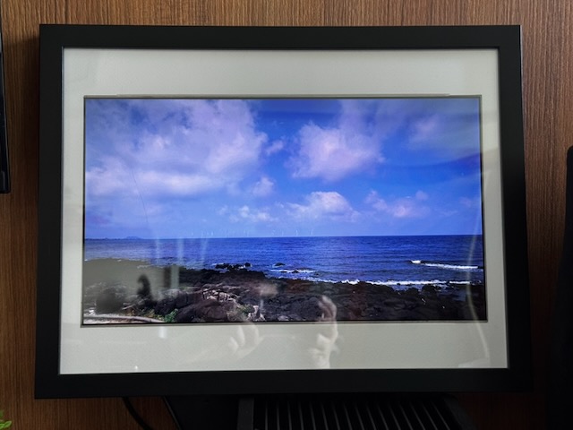
I had an old Asus laptop that I was about to throw out, but it had a pretty decent 15.6″ FHD LCD panel that I thought would be useful, so I decided to turn it into a digital photo frame. I’m writing this blog post due to popular request, but this was done after I had already completed the frame, so not every step has photographs, regrettably.
Bill of materials (in Singapore Dollars):
- Old LCD panel from a laptop, preferably 15.6-16″ – Recycle
- LCD driver board – $20-30
- 12V 2A power supply – $4-5
- IKEA RÖDALM Frame 40x30cm – $10.90
- Rapsberry Pi (3B is enough) – $60
- Short USB cable and HDMI cable for the Raspberry Pi – <$10
- Some competency/knowledge of Linux – Priceless
- Software: FrameOS – https://frameos.net/
- A server somewhere, or your laptop to run the FrameOS server
- (Optional) Some 3D printing design skills, and a 3D printer
Total cost should be less than $120 to make this happen.
Sourcing the LCD panel from an old laptop
This project wouldn’t be financially feasible without an old LCD panel, so you’ll definitely need an old laptop to pull it out from.
The first step is to remove the frame/bezel around the LCD panel. Unfortunately I no longer have the laptop to photograph this, but it is fairly simple: on most plastic laptops, you can either find small screw covers that when removed would expose screws that allow you to pry the bezel off, or some laptops rely fully on clips around the bezel so just start prying slowly – usually from the bottom works better.
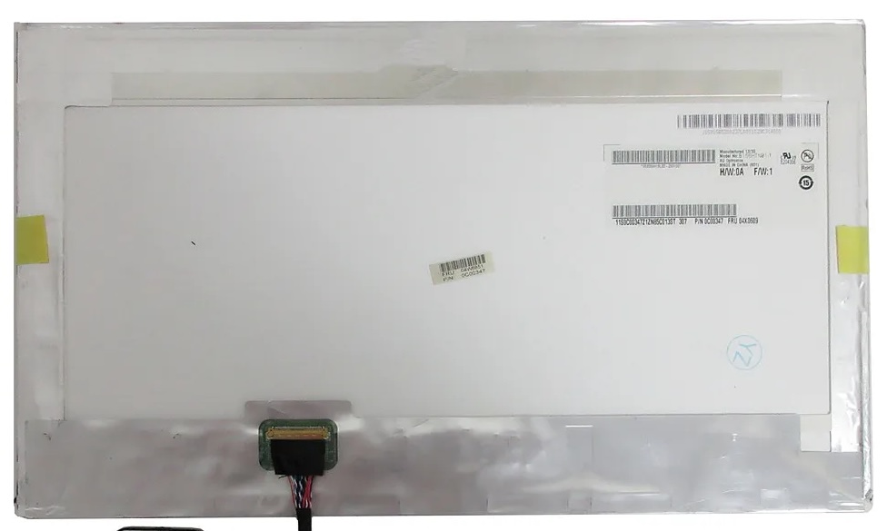
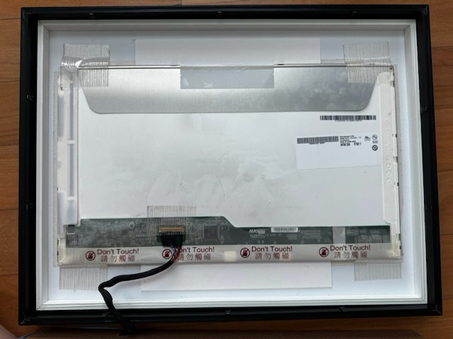
Once you remove the frame/bezel, you will see the LCD panel itself held by more screws. Carefully unscrew them – the panel is fragile, so be careful – and look behind the panel to identify the make and model of the panel. This is usually printed on a sticker or on a barcode.
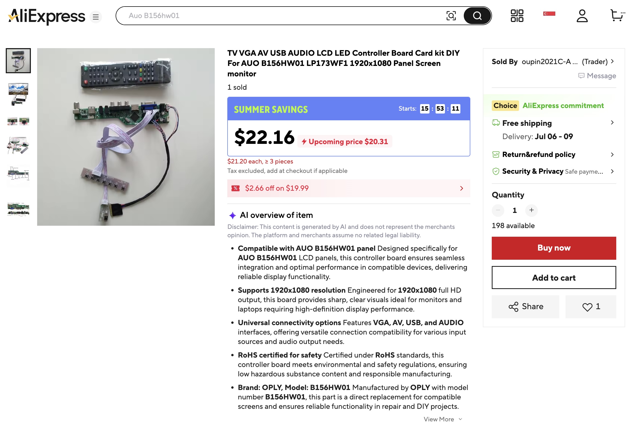
Sourcing the Controller Board for the LCD
Once you’ve identified the make and model, search on sites like AliExpress for a controller board for your panel. You’ll want a board that:
- Accepts HDMI input
- Has a USB port (this is needed to power the Raspberry Pi later)
- Accepts a standard 12V barrel jack power input
These boards are fairly cheap, and typically run for around $20.
Power Supply
To drive the controller board and LCD, you’ll also need a 12V power supply. I have a bunch of these lying around at home, and sometimes you might be able to get one off an old router or home security camera. I pulled mine off an old TP-Link camera.
As for current rating, 12V x 1A (12W) is more commonly found and would work, but if you’re going to buy one, get at least 12V x 2A (24W).
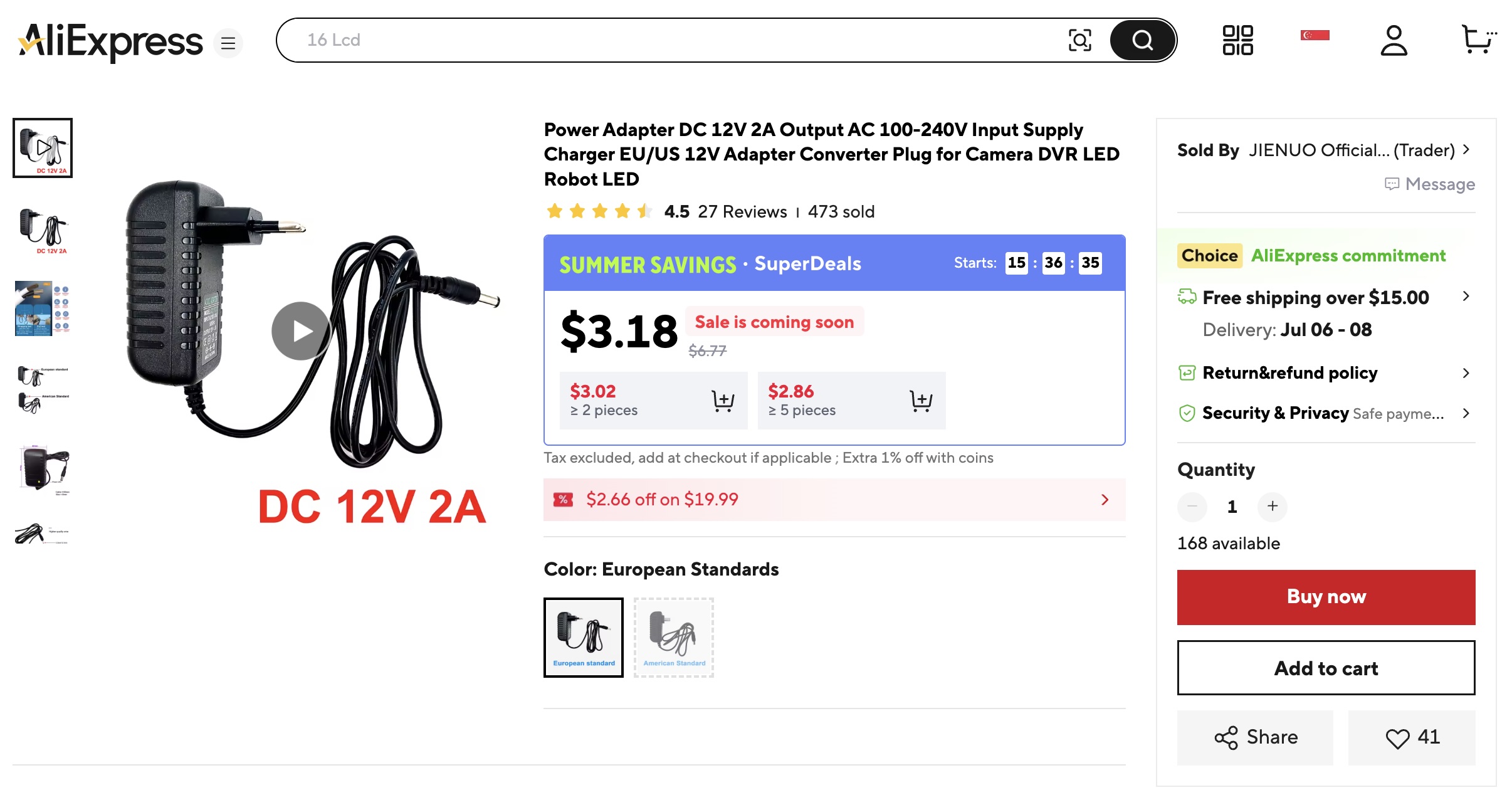
These cheap one from AliExpress can sometimes have questionable quality and ratings, so if you find one from an old reputable brand appliance – it would be better. A typical LCD panel takes about 7-10W & Rapsberry Pi takes around 2-5W, so unless everything is running at full load all the time, you should be keeping under 12W.
The IKEA RÖDALM Frame 40x30cm
I picked this specific frame because of its thickness to enclose the LCD panel, and this specific size because the internal height of the matboard matches the LCD panel (~20cm).
For information, the 15.6″ 16:9 LCD’s viewable area measures roughly 34.5×19.4cm. Your panel might not be the same size, so please measure it.
The internal width of the matboard is only 30cm, so it needs to be cut a little (~2.3cm more on each side).

I also learned later that there are special matboard knives to cut the 45 degree bevel, but I already used a regular box cutter (“penknive” for Singaporeans). Not very pretty though, but probably easy enough to just replace the frame in future.
Mount the LCD on the Matboard
Using a double-sided tissue tape (this works better than regular double sided tape), apply it around the perimeter of the LCD panel and adhere it to the matboard, then add more tape behind to secure it further. I also added a cardboard (these were pieces I cut out of the matboard) at the top and bottom to keep it from sliding.
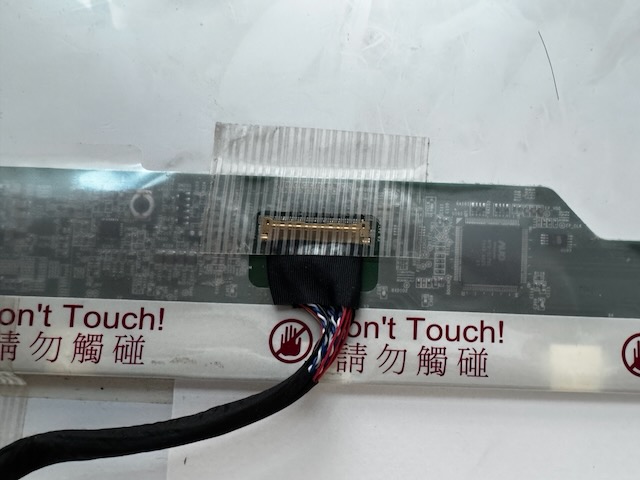
Connecting the Controller Board
The next step is to connect the controller board to the LCD panel, and test it. Tape down the LCD connector at the frame to prevent it from coming loose.
Once you’ve confirmed everything works, it’s time to close up the frame. I made a hole in the frame backing board for the LCD LVDS cables to pass through. Do leave some cable slack inside the frame.
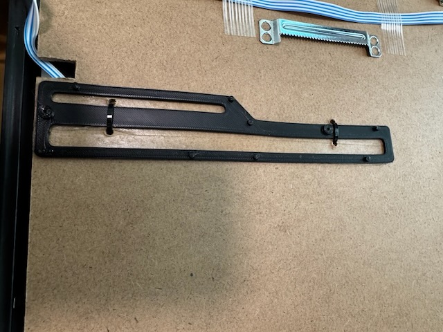
Printing a base for the Controller Board
Frankly it’s rather hard to mount the controller board with all the solder pins sticking out of the bottom, so I made a simple 3D printed base for the controller board.
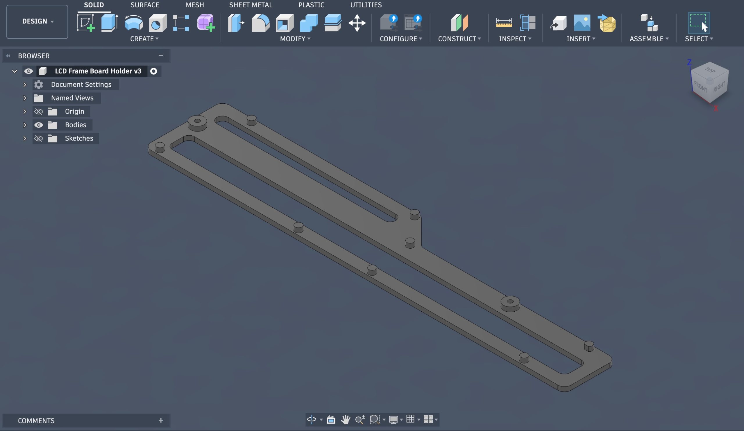
If you don’t have a 3D printer or don’t know how to design one, generous amount of foam tape might probably work.
Mounting Components
The 3D printed controller board base is attached to the back with double-sided tissue tape. I later added zip ties because the heat from the board made the tapes less effective.
I also attached the buttons – menu, power, up/down, left/right for the OSD to control screen brightness, contrast, etc. to the back of the frame with the same tape.
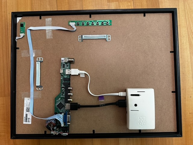
At the top left corner of the pic you’ll also see a small board – that’s the IR sensor for the remote control that came with my controller board. It works this way, as long as the IR can reflect off a wall behind the frame – you’ll rarely use the remote anyway.
The Raspberry Pi (white box) is secured with zip ties. You can see how I power it with the white USB cable from the controller board. The USB cable is short and tidy, but the HDMI cable is too long. I’ve ordered a short 15cm HDMI cable on AliExpress for another few dollars, and will be replacing it.
Software Selection
After experimenting with a bunch of software, including commercial with free plans and Open Source ones like DAKboard, Anthias, OpenFrame, etc. I settled on FrameOS. I won’t deep dive into why I picked it but quick summary is: DAKboard is powerful and nice, but you’ll really need to pay to get any proper use out of it. I found FrameOS (Open Source) the easiest and best for my purpose.
How FrameOS Works
FrameOS software comes in to parts: Server (aka Backend) and Client (aka Frame).
The Backend can be deployed anywhere — your laptop, a NAS, a Proxmox VE server, a Mac Mini, etc. For the more technically inclined, it’s a Docker container running a Python3 web app & Redis.
The Client is your frame which runs on regular Raspberry Pi OS. If you have ESP32 devices, it gets more interesting but that’s not covered here.
Installing the FrameOS Backend
Decide where you want to run the server. For this, I used my Proxmox VE server.
Important: If you’re using a Linux VM, allocate at least 16GB of disk space because the Docker containers need disk headroom to extract. You’ll run out of disk space with something like 8GB.
Run this command to install the FrameOS backend (in Linux):
apt update && apt install curl
bash <(curl -fsSL https://frameos.net/install.sh)
This basically installs Docker, pulls and runs the container frameos/frameos.
If you prefer other deployment methods, such as directly running the Docker container, you can read their documentation.
Once your FrameOS is installed, you should be able to reach it at http://<FrameOS IP>:8989 from your browser. I’ll call this the FrameOS Web UI. Now, create your first user account via the Web UI, then come back to it later.
Setting up the Rapsberry Pi
The Rapsberry Pi needs nothing but a fresh install of Raspberry Pi OS Lite. DO NOT install the full OS with the GUI. You don’t need it.
When flashing your microSD with the Raspberry Pi Imager, remember to configure your Wifi and SSH settings during the process to reduce the need to configure it again later.
Once you’ve flashed the microSD, boot your Raspberry Pi, get its IP address and verify you can SSH to it.
Then via SSH, run:
sudo raspi-configGo to System Options > Admin Password, and disable sudo password. This will prevent issues later.
Deploying the FrameOS Client
From your FrameOS Web UI, add a new frame.
- Select Install over SSH.
- Enter SSH connection details for your Raspberry Pi.
- Select HDMI / Framebuffer as display driver.
- Click Add Frame.
- Click Full Deploy.
The FrameOS Backend will SSH to your Rapsberry Pi and run the necessary shell commands to install the Client packages and turn your Rapsberry Pi into a digital frame.
At this point, you might encounter some errors like I did – for some reason the SSH password needs to be entered again. Click on Settings on the left, and update the SSH password, then perform a Full Deploy again. You might still see an error, but don’t flip out. Click on Logs (on the left) and watch the installation progress.
Once the deployment completes, the Raspberry Pi automatically reboots.
You will see your frame boot up and show a black screen that says no active scene. This is when you’ll set up a scene.
Set up a Scene
From the FrameOS Web UI, select your newly deployed frame, and add a Scene to it. I picked the provided SD card image scene. Tweak the settings as necessary, then activate/deploy it to your frame. Also click on the kebab menu (3 vertical dots) and make it the boot scene.
You can manage your assets by clicking on Assets on the left, and uploading photos into the folder specified when setting up the scene. The default is /srv/assets but it can contain a ton of other junk so I like to create a new subdirectory /srv/assets/photos and upload my photos there.
Done!
And that’s it – you have a working digital frame that can be remotely managed. One last point to note: you can turn off/shutdown the FrameOS server once the settings have been deployed. Have fun!